|
(http://www.cintec.com/en/applications/Archtec/documents/newcomer1.htm.Traducción
por Miguel Ramis)
La nueva tecnología ayuda a mantener
el encanto histórico . Por David B. Woodham,
P.E.
--------------------------------------------------------------------------------
The Newcomer's Mill Bridge in western Maryland is a
historically significant remnant of the first federally
funded roadway, The National Road, which Congress authorized
in 1806. The roadway itself began in nearby Cumberland
and proceeded west- ward. Before the bridges were built,
passengers along this road had to climb up and down
the muddy fiver banks and ford the fiver by wagon, horse,
or foot.
In the 1800s, the stone masonry arch was the most common
bridge type, as it was relatively simple to build under
the direction of a competent mason. The construction
was quite simple. The spandrel walls and arches were
built of stone. The interior was then filled with rubble
and covered with smaller aggregate and soil to form
the roadbed.
According to the Maryland Historical Trust, the Newcomer's
Mill Bridge was built around 1815. This single-span
stone arch bridge crosses the Little Savage River. The
semi-circular arch span is approximately 25 feet and
is constructed of random stone, while the spandrel walls
are constructed in coursed ashlar bond (Figure I ).
The bridge currently provides access for one property
owner and typically carries only cars and light trucks.
Even though these are small loads by modem standards,
they are greater than those envisaged by the original
builders. In 1999, Atkinson-Noland & Associates
was contracted to bring the bridge back to its original
condition. The major deficiency observed on the bridge
was the detachment of the spandrel walls, a common problem
in masonry arch bridges.
The south spandrel wall was dearly separating, and the
north wall was also beginning to separate, as evidenced
by a visible crack between the wall and the main barrel.
In addition, we observed three additional longitudinal
cracks in the arch at roughly eight foot intervals.
Undoubtedly, the bridge required maintenance throughout
its life; however, only the more recent repairs are
documented. Most likely, the mortar joints were repointed
periodically to maintain the structure. In an attempt
to prevent mortar erosion on the underside of the arch
barrel, a layer of shotcrete was applied. The shotcrete
repair is unsightly, and it is not a long-term solution
for this type of structure. As applied, it prevents
the moisture from escaping from the arch baird. In 1991,
the southwest wingwall collapsed and was subsequently
repaired the following year. According to available
records, the south spandrel wall was also rebuilt in
1995.
Many mortar joints near the springing (the location
where the arch meets the
abutment) of the arch were eroded one to three inches
back from the exterior face of the stone. Near the southeast
comer, a large void was present where stone and mortar
had fallen away from the joint between the barrel and
south spandrel wall, as shown in Figure 2.
In order to assess the bridge's capacity, Atkinson first
needed the detailed geometry of the bridge. We retained
a local surveying crew to collect this information.
More than 600 three-dimensional points on the bridge
deck and barrel were collected. The points were gathered
on a variable grid spacing which was fairly coarse overall
(three to four feet on center) but tightened to 18 inches-square
in areas where the geometry was critical (i.e. the quarter
points of the barrel arch and the future locations of
the anchors).
Our firm converted the information to three-dimensional
coordinates, then developed an AutoCAD file as an input
file for the analysis program.
We sent the bridge geometry file to Gifford and Partners
(U.K.) who performed the structural analysis of the
bridge. Because of the many stone arch bridges in England,
Gifford is accustomed to this type of analysis and has
developed a discrete element model, which essentially
models individual mortar joints and stones. The friction/contact
laws were conservatively determined based on the type
of stone and typical mortars from that period. This
model provided an improved prediction of the inelastic
behavior of the arch.
In the 1800s, the stone masonry arch was the most common
bridge type, as it was relatively simple to build under
the direction of a competent mason. The construction
was quite simple. The spandrel walls and arches were
built of stone. The interior was then filled with rubble
and covered with smaller aggregate and soil to form
the roadbed.
According to the Maryland Historical Trust, the Newcomer's
Mill Bridge was built around 1815. This single-span
stone arch bridge crosses the Little Savage River. The
semi-circular arch span is approximately 25 feet and
is constructed of random stone, while the spandrel walls
are constructed in coursed ashlar bond (Figure I ).
The bridge currently provides access for one property
owner and typically carries only cars and light trucks.
Even though these are small loads by modem standards,
they are greater than those envisaged by the original
builders. In 1999, Atkinson-Noland & Associates
was contracted to bring the bridge back to its original
condition. The major deficiency observed on the bridge
was the detachment of the spandrel walls, a common problem
in masonry arch bridges.
The south spandrel wall was dearly separating, and the
north wall was also beginning to separate, as evidenced
by a visible crack between the wall and the main barrel.
In addition, we observed three additional longitudinal
cracks in the arch at roughly eight foot intervals.
Undoubtedly, the bridge required maintenance throughout
its life; however, only the more recent repairs are
documented. Most likely, the mortar joints were repointed
periodically to maintain the structure. In an attempt
to prevent mortar erosion on the underside of the arch
barrel, a layer of shotcrete was applied. The shotcrete
repair is unsightly, and it is not a long-term solution
for this type of structure. As applied, it prevents
the moisture from escaping from the arch baird. In 1991,
the southwest wingwall collapsed and was subsequently
repaired the following year. According to available
records, the south spandrel wall was also rebuilt in
1995.
Many mortar joints near the springing (the location
where the arch meets the abutment) of the arch were
eroded one to three inches back from the exterior face
of the stone. Near the southeast comer, a large void
was present where stone and mortar had fallen away from
the joint between the barrel and south spandrel wall,
as shown in Figure 2.
In order to assess the bridge's capacity, Atkinson first
needed the detailed geometry of the bridge. We retained
a local surveying crew to collect this information.
More than 600 three-dimensional points on the bridge
deck and barrel were collected. The points were gathered
on a variable grid spacing which was fairly coarse overall
(three to four feet on center) but tightened to 18 inches-square
in areas where the geometry was critical (i.e. the quarter
points of the barrel arch and the future locations of
the anchors).
Our firm converted the information to three-dimensional
coordinates, then developed an AutoCAD file as an input
file for the analysis program.
We sent the bridge geometry file to Gifford and Partners
(U.K.) who performed the structural analysis of the
bridge. Because of the many stone arch bridges in England,
Gifford is accustomed to this type of analysis and has
developed a discrete element model, which essentially
models individual mortar joints and stones. The friction/contact
laws were conservatively determined based on the type
of stone and typical mortars from that period. This
model provided an improved prediction of the inelastic
behavior of the arch.

Figure 1: Vista del paño de la pared sur mostrando
la localización de grietas reparadas y anclajes de
emergencia en los riñones (spandrels).
 |
Figura 2: Deterioro severo en la esquina suroeste
mostrando separación de la pared spandrel del
arco barrel y el resultante vacío.
Figura 3: (abajo) Sección a través del arco
mostrando los típicos ARCHTEC anclajes tensantes
instalados tangencialmente al intradós al cuarto
span (las dimensiones mostradas son en metros.). |
method has been correlated with a number of laboratory
experiments with good results. The bridge was analyzed
with and without the anticipated repair anchors, This
analysis indicated that four, one-inch diameter ARCHTEC
anchors were needed to reach the required load capacity
of the bridge and to pre- vent a hinge from forming
in the arch barrel. ARCHTEC is a proprietary anchor
system designed specifically for this purpose. Repairs
began in November of 1999.
The construction team first repaired major voids and
rebuilt areas where stone had fallen away from the bridge.
The voids near the springing of the arch were repaired
using low-pressure grouting techniques. Injection ports
were drilled on two-foot centers through mortar Dints
in the masonry. A compatible cementious grout was injected,
beginning at the lowest elevation, at pressures of 10
psi or less. This work continued to a height of approximately
six feet above the stream bed. One localized area had
to be stabilized before we could begin drilling the
larger anchors through the structure.
We installed 20 small Cintec anchors (two feet long,
3/4 inch in diameter\} in the south spandrel wall. The
Cintec system of reinforcement was developed in Europe
beginning in 1965 and consists of stainless steel reinforcing
bars that are surrounded by a fabric sock. The anchors
are installed in oversized core holes and then injected
under low pressure with a proprietary grout. The grout
inflates the fabric sock around the anchor to provide
both a chemical and mechanical bond with the interior
of the core hole.
Holes for these anchors were drilled on a grid of
roughly two feet by two feet. The holes were drilled
through the face of the stone in order to tie the large
stones to the rubble above Client Maryland DOT Project
management CLS Cintec America Masonry contractor Masonry
Solutions Inc. Structural analysis Gifford and Partners
Mr. Woodham is vice president at Atkinson- Noland &
Associates in Boulder, Colo., a consulting engineering
firm specializing in evaluation and repair of existing
structures the arch. The anchors were recessed two inches
into the stone core, and the holes were patched once
the anchor had been installed and grouted, Sixteen Cintec
anchors (six feet to 10 feet in length) were installed
on the south and north spandrel walls to tie the walls
together with the arch barrel, making these elements
act compositely.
In addition, three, 29-foot anchors were installed
connecting the north and south spandrel walls to prevent
further separation. Four main ARCHTEC anchors were installed
from the roadway of the bridge and designed to pass
tangentially near the arch intrados at the quarter span
(Figure 3]. For efficiency, the 14-foot anchors had
to pass as close to the intrados as practically possible
-- in this case, within four inches (10 an.) of the
intrados. In order to achieve the proper placement of
the reinforcing, we needed to layout the location of
the anchor entry point and the vertical and horizontal
angles carefully. According to Wayne Ruth of Masonry
Solutions, "New masonry coring equipment both simplifies
and accelerates the installation of the longer anchors."
With nearly 300 feet of coring the new equipment made
a big difference. We successfully demonstrated the strengthening
of a historic structure using ARCHTEC anchors with minimal
invasion. The use of internal reinforcement did not
alter the appearance of the structure, nor did the installation
cause major disruption to its use. An advanced structural
analysis technique allowed the composite behavior of
the reinforced masonry to be predicted accurately and
therefore was a more efficient use of the reinforcement.
We restored the appearance and durability of the bridge
and prevented moisture from entering the masonry with
crack repairs and mortar repointing. Also, we penetrated
the shotcrete liner covering the arch barrel periodically
allowing moisture to escape.
--------------------------------------------------------------------------------
Credits
Client Maryland DOT
Tech. & site support Akinson-Noland & Assoc.
Project management CLS Cintec America
Masonry contractor Masonry Solutions Inc.
Structural analysis Gifford and Partners
Surveying Specs Surveyors
Mr. Woodham is vice president at Atkinson- Noland &
Associates in Boulder, Colo., a consulting engineering
firm specializing in evaluation and repair of existing
structures
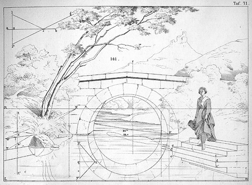
En este estudio de perspectiva el autor nos
muestra la técnica que se esconde tras
la belleza del cuadro. El reflejo del agua nos
devuelve la imágen invertida del arco,
la piedra y los escalones.
Streckfuss, Wilhelm:
Atlas zum Lehrbuche der Perspective
für den Schulgebrauch und Selbstunterricht
(Zweite Auflage Breslau : Verl.
Eduard Trewendt, 1874)
|
 |
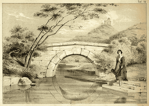
| Cuadro ya terminado a partir del estudio de perspectiva
anterior. |
|
Otra versión del mísmo caso,
por otro autor.
Schreiber, Guido:
Lehrbuch der Perspektive mit einem
Anhang über den Gebrauch geometrischer Grundrisse
(Dritte Auflage Leipzig : Alfred
Oehmigke's Verlag, 1874)
|
|
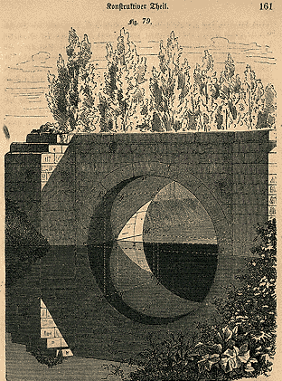
Estudio de sombras sobre un puente visto desde
la cara norte, al atardecer.
Schreiber, Guido:
Die Schattenlehre : für Architecten,
Techniker, Mechaniker und Bauhandwerker,
für Bau- und polytechnische,
höhere Gewerb- und Realschulen
(Leipzig : Verl. von Otto Spamer,
1868)
|
|
Ver puentes |